By TODD YATES, PE, TBE, CxA, LEED AP BD+C
With the increasing use of chilled beam systems, most of us today are familiar with induction technology. Many active chilled beam systems use some form of recirculation fan or other constant volume supply to provide primary air, usually mixed with conditioned outside air to meet ventilation requirements.
A flow hood cannot be used to measure airflow on active chilled beams since the hood disrupts induction and the normal operation of chilled beam airflow. Instead, airflow to each chilled beam is determined by measuring the air pressure drop at a factory-mounted port and using the manufacturer-provided Cv or flow chart to convert that pressure drop to airflow.
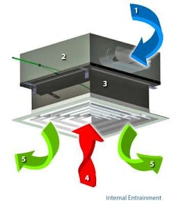
Induction diffusers have no coils with which to heat or cool. They are used in conjunction with low temperature primary air (typically 48 deg. F). This allows the designer to use smaller AHU’s and associated ductwork to deliver conditioned air to the occupied spaces.
The diffusers induce room air which is mixed with the low temperature primary air before being diffused into the room. Determining airflow is similar to chilled beams.
Induction diffusers include a factory-mounted port where pressure drop is measured and converted to airflow by using a manufacturer-provided Cv or flow chart.
As noted above, chilled beam systems often utilize some sort of constant volume fan system to provide primary airflow to the chilled beams and the pressure drops are used to proportion the airflow to multiple chilled beams. The induction diffuser system on this project utilized a conventional AHU with mixed air, along with conventional VAV’s with reheat coils.
Since we had not previously balanced a system exactly like this one, and this system was new to this particular owner, as well, we made sure to take some time to evaluate the designed sequence of operation and to plan our approach carefully to what was a slightly out-of-the-ordinary system. We began by using duct traverses to calibrate the VAV’s.
Following that, we planned to use the pressure drop at the induction diffusers to proportion the outlets, since flow hood readings are not possible with the induction system. It was then that we discovered that the duct traverses were typically lower than the induction diffuser total. Of the eight units we sampled, one was off by about 40% and one only by 2%, while the others averaged about 22%. (See Table 1.)
We also tested four different diffusers on the low pressure side of the VAV’s. The results appeared to be slightly better, where the readings differed only by about 15%. (See Table 2.)
Meeting of the Minds
Since this building had over 600 induction diffusers, we did not want to proceed and submit a report that might not be approved. We wanted complete clarity, so we requested a meeting with the key stakeholders to discuss our initial measurements and agree on the methodology to use in balancing the system. In attendance were the owner, designer, mechanical contractor, and equipment manufacturer.
The documentation provided by the manufacturer says this:
NOTE: Do not attempt to confirm the primary air flow quantity by conventional Pitot-traverse methods in the primary air ductwork. Low duct velocities and boundary layer measurement inaccuracies do not permit accurate measurements of duct velocities for primary air installations.
That’s simple enough to execute. But if there were warranty call backs, could we defend our methodology? Or would someone demand a duct traverse to confirm design airflow?
We know most of the duct traverses would yield different results than the sum of the induction diffuser readings.
The meeting was interesting and informative. Many ideas were discussed, including empirically deriving new Cv’s for the induction diffusers based on duct traverses. Beyond the manufacturer’s admonition NOT to do that, the key piece of information that ultimately convinced everyone that the induction diffuser Cv calculations were the best method were the results from VAV-12 and VAV-13. These VAV’s are identical in size and only 10 CFM difference in setpoint. The difference in the traverse and induction diffusers on VAV-12 is 22.7%, while the difference on VAV-13 is only 1.3%. Why would this be true and what does it tell us?
Let’s consider the ducts supplying these two units.
VAV-12 has a 12-in round duct from the main and it transitions down to 6-in round directly before the VAV. VAV-13 on the other hand is fed from the main by a 6-in round duct. While the first thought might be that the VAV-13 could have excessive restriction, that is not the case and in fact the smaller duct is the key to understanding the problem. VAV-12 and most other units have larger duct supplying them, which reduces potential static pressure drop, but also dramatically reduces the required velocity. VAV-12 requires only 494 FPM, where VAV-13 requires 1900 FPM.
To understand why that matters, take a simplified look at the duct velocity and corresponding velocity pressures.
The measured flow on VAV-12 would require a velocity pressure of 0.015-in. The measured flow on VAV-13 would require a velocity pressure of 0.236-in. This can be seen in Table 1. Compare that to the typical differential pressure readings at the induction diffusers in Table 2. That shows pressures of approximately 0.065-in to 0.175-in. These larger differential pressures at the induction diffusers result in more accurate, repeatable readings. The agreement between the sum of induction diffuser readings and the higher velocity duct traverse on VAV-13 is consistent with that concept.
Lessons Learned
Operating Principles of Induction Diffusers: Induction diffusers utilize low temperature supply air from a primary air source, along with room air induced into the diffuser resulting in a higher temperature air distribution into the occupied space. This allows the use of smaller AHU’s and smaller ductwork where space above the ceiling is limited.
Balancing Induction Diffusers: Like chilled beams, direct flow hood readings are not possible with induction diffusers. Airflow can only be measured with the pressure drop at the diffuser and the Cv or flow chart provided by the manufacturer.
Alternative Measurement Methods: Alternative measurement methods of measurement cannot typically be applied to induction diffuser balance. If alternative methods are used, care must be taken to ensure that the ranges and instrumentation are appropriate.
Communication: Effective coordination with project stakeholders on technical issues and expectations should always be considered, especially when the systems are new to the team or utilize unusual equipment or sequences. Ideally, these discussions should include the owner, designer, mechanical contractor, and equipment manufacturer.
##########
This article was adapted from the AABC TAB Talk Webinar Airflow Measurement & Control with Induction Diffuser Technology (aabc.com) presented by AABC member, Todd Yates of Synergy Test & Balance, Indianapolis. Email: [email protected].


